 The Hairspray-can antenna.
Directly
to the programs
C-goals
The Hairspray-can antenna.
Directly
to the programs
C-goals The Hairspray-can antenna.
Directly
to the programs
C-goals
Dear Ham operators and SWL's, many question about my special antenna are received on my E-mail box. And here now a building description about it. I talk to you that my antennas are builded from my owm formulars and the basic informations are from "Rothammel Antennabook vers. 10, side 123". Also I needed the knowledge from two scientists Mr. Landstorfer und Mr. Meinke.
Ok and now the buildinginformation from my haarspraycan antenna.
For example an antenna - used for 40 meterband. Material are an empty hairspray-can with 50 mm diameter and onlylambda/200 long (200 mm), a grey waterpipe app. 150 to 250 mm long, a PL-connector, the cover from the can, app. 7.5 m isolated wire 1 mm diameter, cable choke with FT-140-43 ferrite ring and app. 7.02 m Coaxcable RG-58. The antenna works up to 150 watts. If you use a wire with 2 or 3 mm diameter and a bigger ferrite ring, you can work more then up to 1000 watts.
A hairspray-can with 50 mm diameter match into the pipe where the pipe is bigger (for the next pipe). Put the hairspray-can with the spraybutton first in the pipe. Is the box an alubox, then drill a hole into it in the near of the spraybutton and screw a soldertab for the following serialcoil.
If the material soldering then of course solder it directly on the can near the button. ATTENTION: some can have no electrical contact between the head of can and body!
You need app. 45 turn for the serialcoil around the pipe directly behind the hairspray can. (exactly goles you can calculate with my calculationprograms) Now put the wire from upperside into a small drilled hole (diameter from the wire) short before the pipe will be bigger, and let the wire a few cm out the pipe.
Now solder the wire on the soldertab or an the hairspray-can directly and pull the wire into the pipe. So also will the can slide into the pipe. Now turn the wire 45 times around the pipe. On the end of the coil also drill a small hole and put the wire into the pipe. In the near of the coilend, drill a bigger hole, so that a PL connector goes into it (sketch example 1). I builded my last antennas with close pipe. Closed with the cover of can and there I put in the PL-connector (sketch example 2).Solder now the end of the coil to the connector and screw the connector into the pipe or glue it with two components glue. Have a look on my sketches.
For final tuning you need a small telescope antenna (app. 30 cm long). Now drill a hole into the bottom from the can and put the telescope antenna into the bottom. If the can soldering then solder the telescope antenna on the bottom so that the antenna goes total into the can. If it not soldering, screw or rivet a soldering sheet metal with 2 rivets on the can bottom in the near of the connection hole. Now you can solder the metal with the telescope antenna. After this take a good glue for all.
With the small 30 cm length tuning antenna you can tune 700 Kc.
Now pull the telescope antenna up and down for best resonance on the transmitting place. The feed cable RG-58 must be 7.02 meter long (49.5/f in Mc). Now connect the cable choke on the end of the feed cable and after the chocke app. 6 meter to the trx. Thats all......
Values of experience of the capacities of hair spray tins antenna to DL7AHW:
My construction manual sees a capacity of about 7 pF for 40 meter band, besides the reel has about 44 windings. Thus one can change with adding or decreasing of 1 to 2 windings the resonance frequency slightly. Would be the C too big and one has e.g. only 3 windings on the coul - how wants one to reach with 3 windings +1 or -1 here a slight resonance change? Does not go! So at least 30 - 50 windings shout exist for the low frequency. A little bit more windings for low frequencies are ok. From 20 meterband reach 15-25 windings.
Approx. 25-50 pF for 160, 15-25 pF for 80, 7-16 pF for 40, 4-10 pF for 20, 1-5 pF for 10 and last 1pF for 6 meterband.
Charts LC ratio and optimal values for CAP-antennasThe windings will be calculated with my program and from there the capacities resolts.
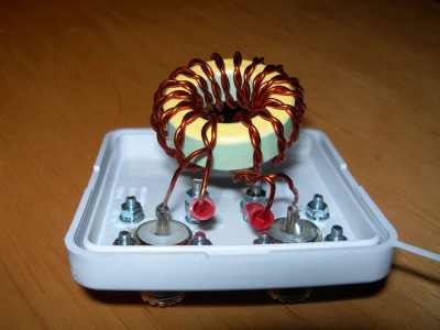
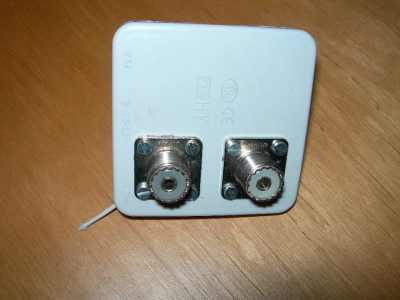
Building a cable choke
Simple wind 12-13 turns RG-58 around a ferrite ring and solder right and left from the coil a PL connector. Let the length from the coaxcable short app. 5 to 10 cm - not more. If you have smaller ferrit rings, you can also build it with drillt pair of isolatet copper lacquer wire 1 to 2 mm diameter. The drillpeaks must be 3-5 mm from eachother so the impedance is 35 to 40 ohm. Very good for the capacity antennas because its will be cooler like the other cable choke.

Now asseble the hole antenna as following:
Sold the coax cable (7.02 meter) with the innerwire to the coil directly or sold a plug on it and screw it on the PL-connector. angeschraubt. If you have soldered directly, please reinsulate the roundet copper 1 to 2 cm away from the cable. Fix the cable with insulating tape on the plastic tube. If you tuned the antenna, then glue it to the tube. Now screw thw cable choke to the other side and then with 5 m coax cable to the transceiver. The length of the cable to transceiver is not important. Thats all.
Now found the point of resonance. It shout be higher like the middle frequency if you test it in your living room. Best is the end of hamradio band (3.8; 7.1 Mc) because out the hous the coax cable has a better contact to earth and the resonance point goes a lower frequency. With the small telescope antenna you can found the exactly point of capacity.
The program explains itself. Only enter the data what you want into the fields where the backgroung is white and click on "Data calculate". To the areacalculateion is still to be said that here not the whole body are calculated, but only the surface which is required to the build of the tension field. With a round body these are the exterior surfaces of the cylinder and the upper ground / head surface. The lower final surface is not incorporated in the calculation. The same infact to the rectangular form. So the sides and the upper head surface. With the ball I have accepted the whole surface, because it can be easily mounted on a thin connection and the coil hangs under it. Also with the input of the surface of some forms I have drawn the whole surface to the calculation which is given. The input of the desired resonance frequency should move at the end of the radioband. To come down with the frequency makes no problem with the tuning antenna, but a higher frequency with inserted tuning antenna will be difficult. Then one would have to reduce the inductivity by short-circuiting some round of wire. The program can be also served with a mobile phone via Internet. A lot of fun with it.
![]()
73 Arthur DL7AHW
Country visitors since 03.07.2010