
Formulas and calculationprograms for matching wire antennas.
|
|
|
What you have is a wire with a length ld and the diameter d. This wire will be suplied on the end with hf-voltage from a transmitter with output resistance 50 Ohm. P is the power of trx.
First what we need is Lambda from the wire.
VK is the shortingfactor. It shout be 0.955 .
If you want to build a vertical radiator (like a car antenna) the effective length lw is
 (F0)
(F0)
In this case please calculate farther with this parameter lw .
We want calculate a horizontal wire antenna. It is very simple to build and low costs.
The slenderness ratio from the antenna is  (F1) and Lambda
  (F2)
(F2)
Radiation resistance of wire:  (F3) or
  (F4)
(F4)
The maximum current will calculate with maximum trx power and the restistance on the real wire input. If you use a dipole the wire input resitance is perfect like 76.6 ohm. In our reality case we calculate with 60 to 70 ohm. Is is build from the effective resistance and the losses resistance. We calculate with 70 ohm.
The half of dipole wire is  (F5)
(F5)
The max antenna current now  (F6)
(F6)
Max voltage is following  (F7)
(F7)
After this script you will see a sketch it shows the relationship between imaginary and the real part, also the angle between it. If the angle = 0 or 180° the imaginary part is also 0. If you have a coil, the voltage is more quickly like the current. On a capacity we have the other case. Is the antenne too long, both pointers ( a+jb = U and b = I ) are on the positve side. If only one pointer different like positve, the antenna is too short and the imaginary part will be negatve. You know R = U/I . If U or I positive or negative also R (Zw) will be positiv or negativ.
If the tan phi positive (0-89.999°, 180-169.9999°, 360°-.... etc) also the antenna is too short if it negative the antenna will be too long 90, 270 (...+180°) deg. If we have resonace the imaginary part will be 0.
The imaginary parts from U and I will be added and the result describt the kind of antenna (capacitive or inductive).
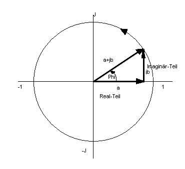 Picture 1
Now we calculate the angle phi ( ) and the tan () .
It is better if we calculate with the radiant measure 360° = 2Pi. Lambdaquarter Pi/2 or 90°. If we have an angle like 90° (+ 180° +180°+.... etc.)the tangents goes to endless !
Now we search an angleline where Umax/Imax equal Phi is.
The angle phi will be calculate by Length of wire in ratio with lambda of trx fequency.
 (F8)
(F8)
f is the frequency in mega hertz.
Now test the antenne: if it capacitive (-j) or inductive (j)? Then calculate the impedance.
 (F9)
(F9)
If Z now negativ, we have Z=Xc also a capazitive antenna, it is outside oft resonance. We make it in resonace with a induktive reaktance Xl, witch must have the same reaktance like the Xc.
No problem......... Xc=Xl Inductivity L:  (F10)
(F10)
f in hz Xl in Ohm.
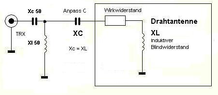
Now we calculate the 50 ohm matching coil (have a look on the sketch). First we need the factor Rp vs. Rs.
Rp is the primary (50 ohm) an Rs the whole coil. ü  (F11)
(F11)
couple Xl is now: Xl ü Xlk
ü Xlk ü (F12)
The match coil is now: Lxlk =  (F10)
(F10)
We have now all goals an we start the winding calculation.
My own formula:  (F13)
(F13)
Formular from a book  (F14)
(F14)
My own formula
 (F15)
(F15)
Formular from a book  (F16)
(F16)
N is the winding goal, d in cm is the coil diameter, l in cm is the coil length and L in µH the induktivity.
The coil length is first time unkwon. We take a beginning length approx. 5 cm. If we have the first solution we calculate again with the calculated windings ,mutiplcate with diameter, free length between the windings and the new length. Now we put it in the formula and calculate again. I think with 4 times calculation we will get a good conclution.
l = (N * coil diameter )+ ((N-1) * windings distance) (F17)
l2= (N2* coil diameter )+ ((N2-1)* windings distance) etc. to l4
Last we calculate the matching coil and we are ready of great mathematical work hi hi hi.
If we view the matter of a too long antenne, we can use the same formula, but for Xc calculation we must use the following formula:
 (F18)
(F18)
Nwe is the calculation of the efficency with new mathematical formulas. By a example the formula for a range of 10 to 180 degrease is following:
Rwirk= ((0.000120*x^3-0.0045*x^2+0.2*x+0.1)^2)/100 (F19)
x is the angle in degrease. If the resistance calculated now it's easy to make a transform from TRX to antenna resistance. Now the formula for Xc50 and Xl50:
Xc50 = - Rg*((Rwirk/Rg)-1)^0.5 [Ohm] (F20)
C50 = 1/-(j*w*Xc50) [pF] (F21)
Xl50 = Rwirk/(((Rwirk/Rg)-1)^0.5) [Ohm] (F22)
L50 = Xl50/+(j*w) (F23)
The w is Omega = 2*pi*f and Rg is the impedance from the RF-generator (52 Ohm). Are all goals known, you can calculate the coil windings, coil length and wire length of L50.
DL7AHW
Hochfrequenztechnik I J. Kammerloher, 1938, 2. Editio 2: F0, F1, F4, F5, F7, F8, F9, Bild1.
Uni Karlruhe lecture script "Eingangsimpedanz von Stabantennen (F6.29) from Prof.Dr.Ing. W.Wiesbeck 2005: F3
General physik "Ohmsches Gesetz": F2, F6, F10, F11, F12, F18,F20-23
Own formulas by DL7AHW: F13, F15, F17,F19
Formulas from "MINI-RK-Program" by Wilfried Burmeister DL5SWB: F14, F16
Visitors since 06.07.2010